
Most of the work so far has been pretty fun and interesting, but now it’s time for the tedious part: wiring every device and LED across the entire panel.
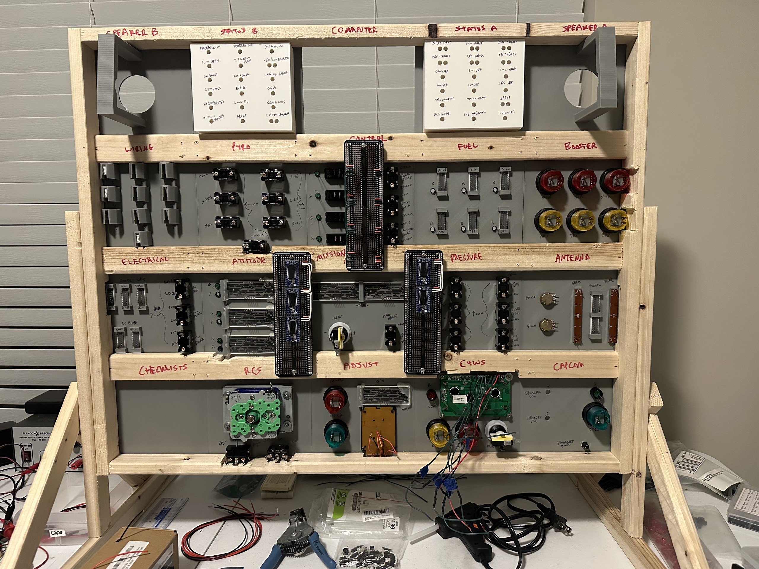
I started by building the small protoboards that hold the LED drivers and I/O expanders (see the Electronics post). I put them in the middle of the panel to keep the wire runs as short as possible. I created many detailed spreadsheets to plan the wiring and optimize groupings to reduce wire counts.
Then I got out my spools of wire and started soldering. This took a lot longer than I expected and I ended up spreading this out over several weeks while I also built the desk. My tracking spreadsheet made it easy to pick right back up where I left off from the previous wiring session.
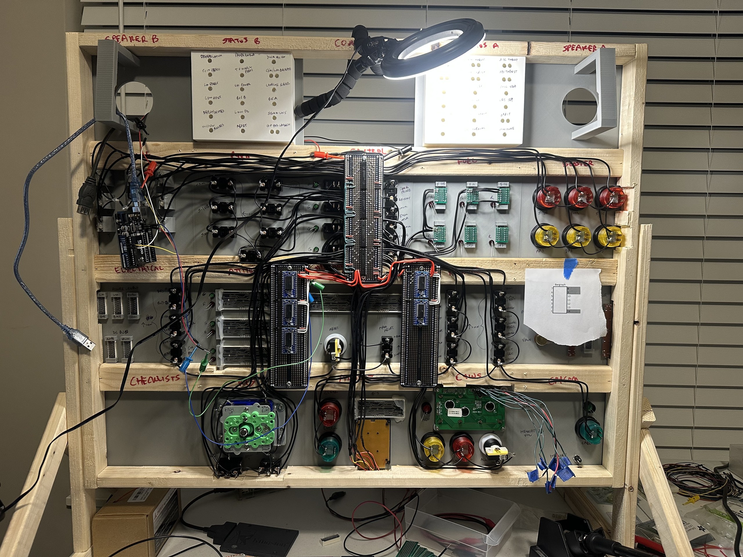
In hindsight, I should have had circuit boards made for each panel and connected them with standard ribbon cables. However, I hadn’t written any of the simulation code yet so I assumed the design would change after testing. I didn’t want to wait for new boards to be manufactured for every change and drag this project out any longer.
Testing
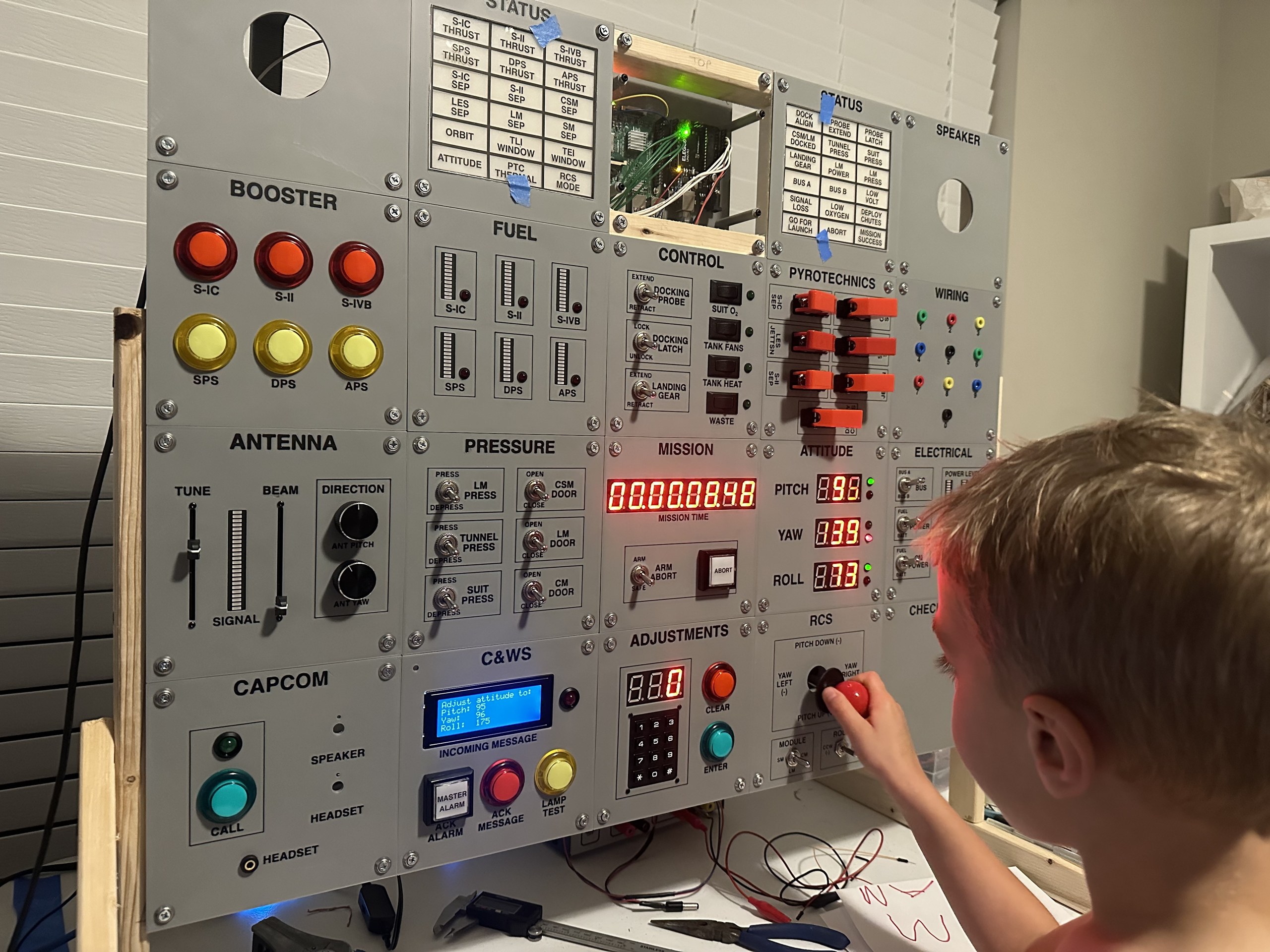
I tested as I went, and I even had a few test engineers come along to help. Rework is one of the worst things to spend time on so I made sure to test frequently before moving on to a new panel.
One final pass of hot glue and zip ties and the wiring was basically complete. It’s a total rat’s nest and repairs will be difficult, but I did my best to run wires over the wooden frame or between components just in case I needed to access components in the future.
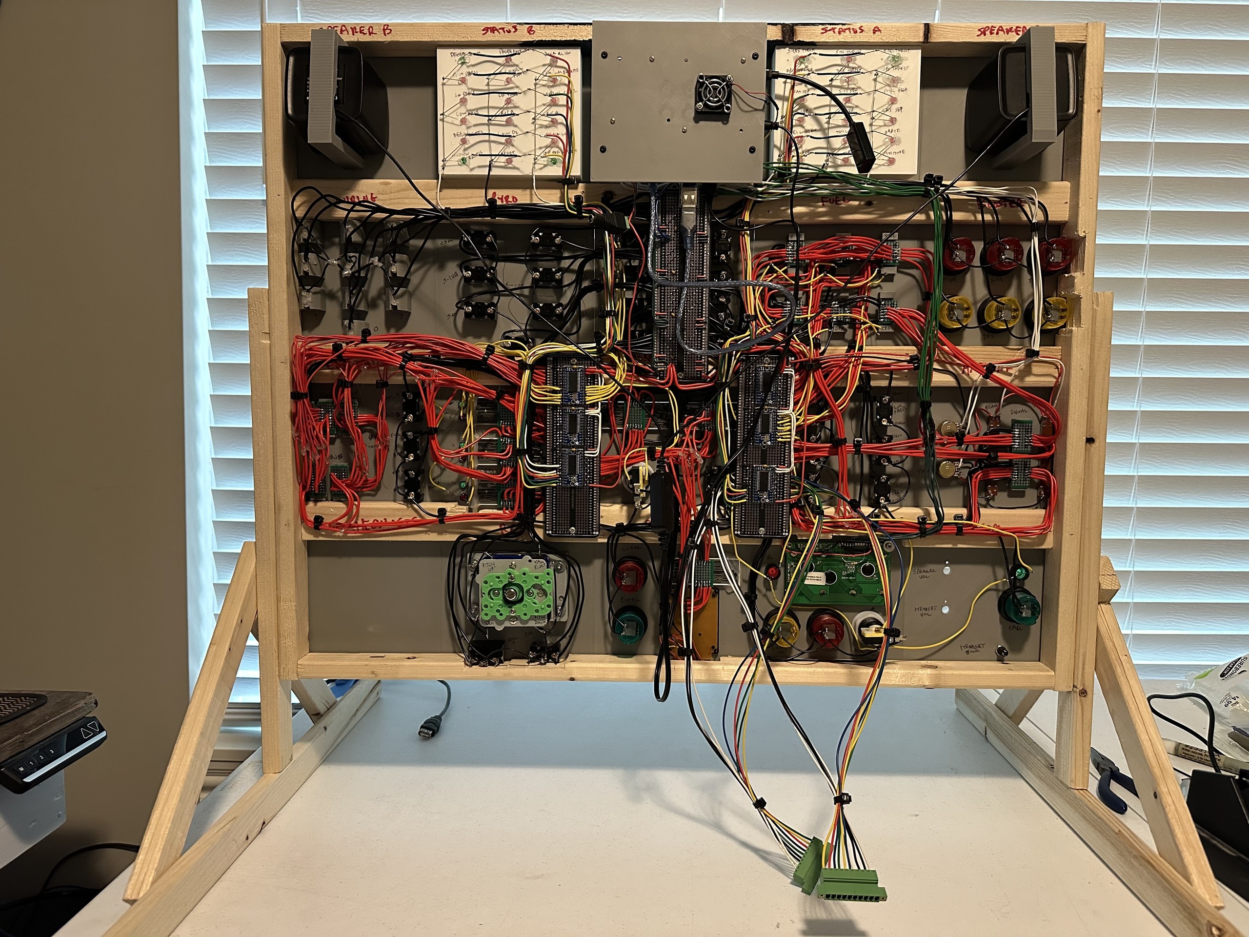
The green connectors hanging off the bottom are for the Mission Map. The only items not complete in this picture are the audio controls in the bottom right. There are two volume knobs and an headphone jack missing. I plan to finish those up later as they aren’t needed for the simulation and interface directly with the Pi.


Leave a Reply