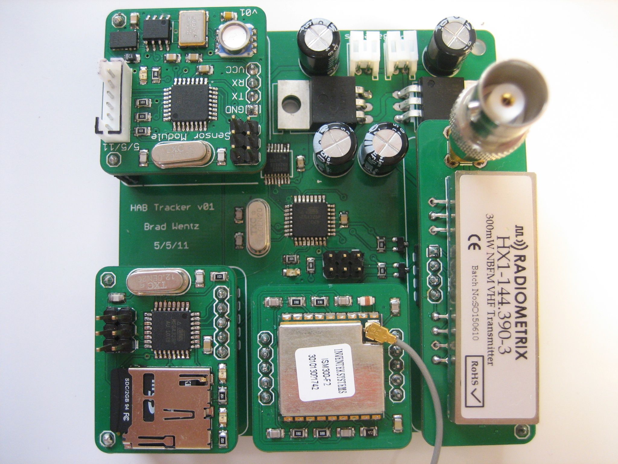

The electronic components on my high altitude balloon work together to gather, store and transmit various types of data from several sources. Some of the data is vital (latitude and longitude coordinates) and some is just for fun (pressure, temperature, etc.). I took this into consideration while designing my hardware. The block diagram below shows the main components and the flow of data between them.
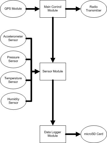
Separating everything into three modules increases the number of parts and power consumption. It makes up for this by reducing the processing burden on each microcontroller, reducing the impact of software bugs or hangups, and allows for much easier debugging during development. I can also reuse modules (such as the data logger) in future projects. The one-way data flow from the most important module down to the least important also prevents software bugs from impacting the key function of the control electronics: reporting the balloon’s location.
Main Module
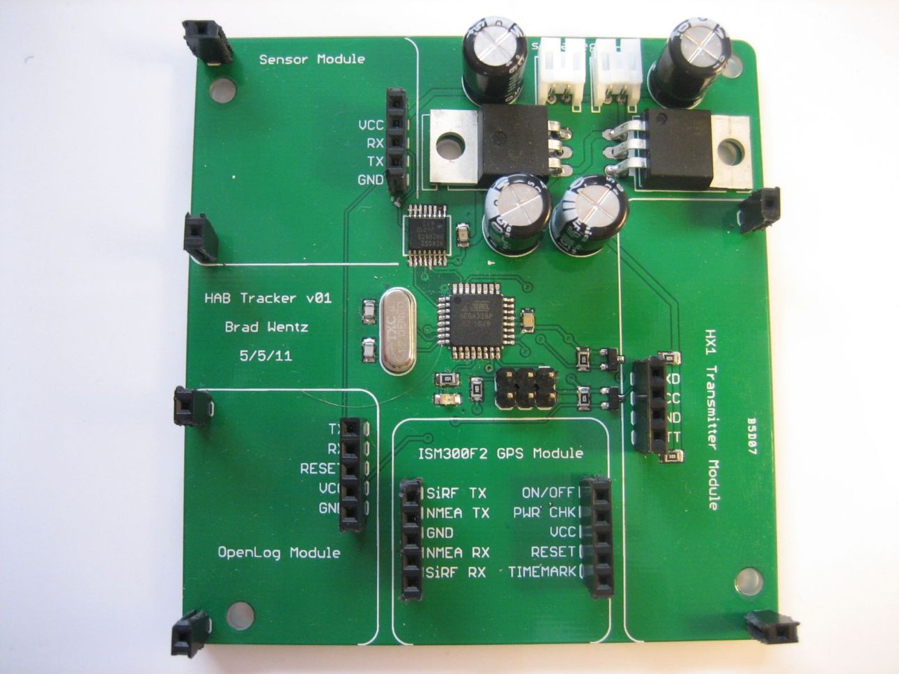
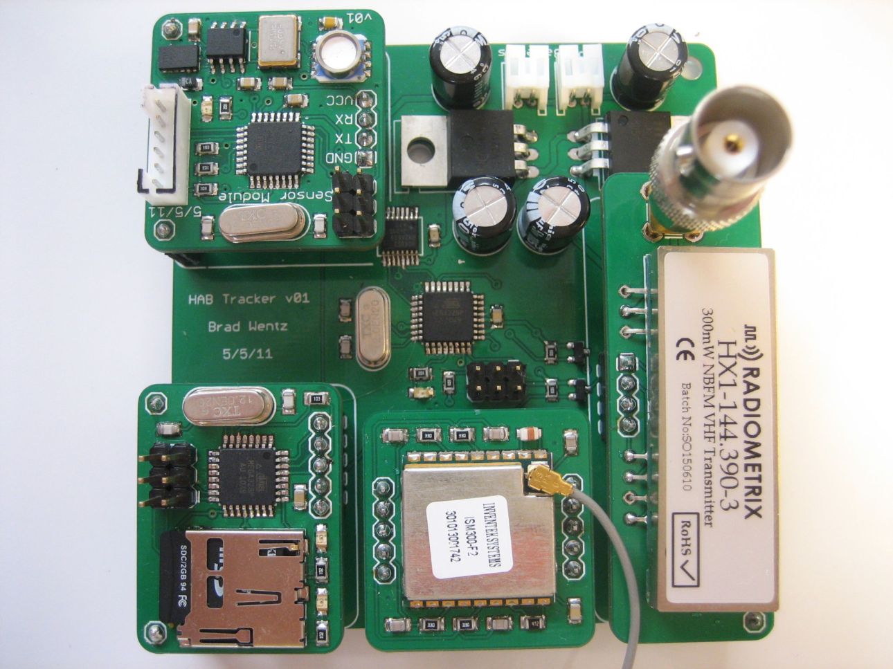
The main module consists of a microcontroller, GPS module and radio transmitter. This module is dedicated to handling the incoming GPS data and sending it where it needs to go. Most importantly, it transmits the GPS coordinates over the radio transmitter so the ground team can track the balloon’s location. This information is broadcast once a minute to conserve power and leave the APRS frequency free for others to use. I used the open source Trackuino APRS tracker code as a base for my main module. Only minor modifications were needed for my GPS module.
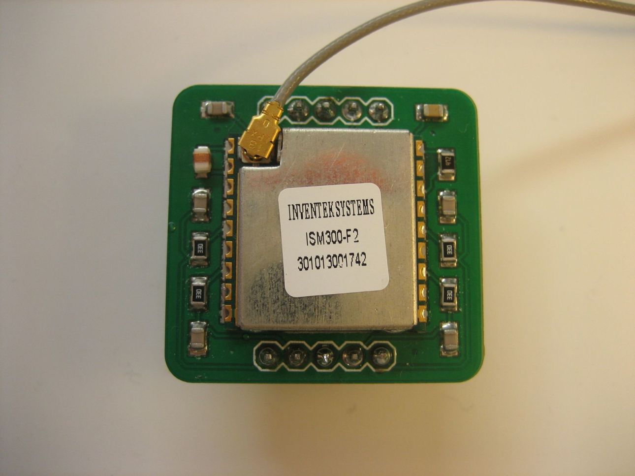
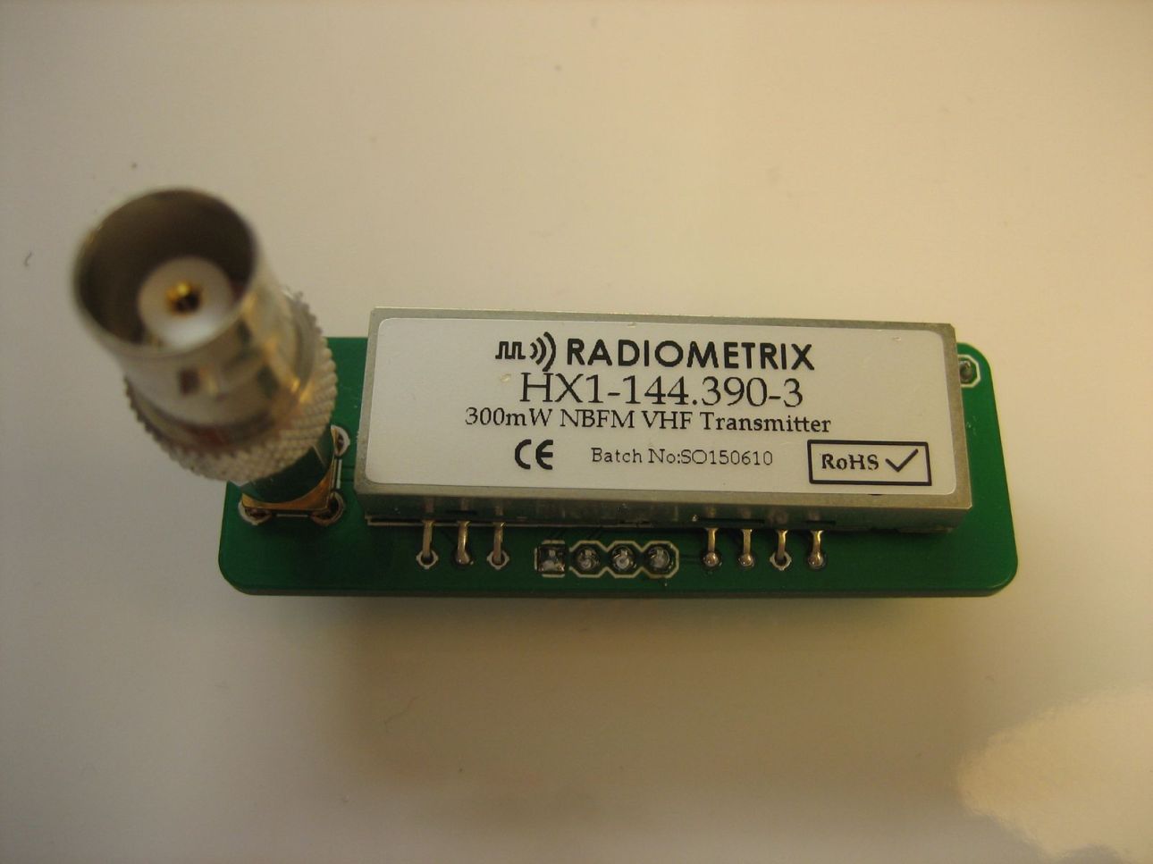
Even though radio transmissions only occur once a minute, new GPS data is received about once a second. I don’t want to throw away all of the GPS data that is not sent over the radio. Instead, all GPS data is also transmitted via serial UART to the sensor module so it can be logged for later analysis. This is a one-way transmission and the sensor module does not respond even if an error occurs (it actually can’t respond because the RX line is not connected). This prevents a malfunction of the sensor module from locking up the main module.
Sensor Module
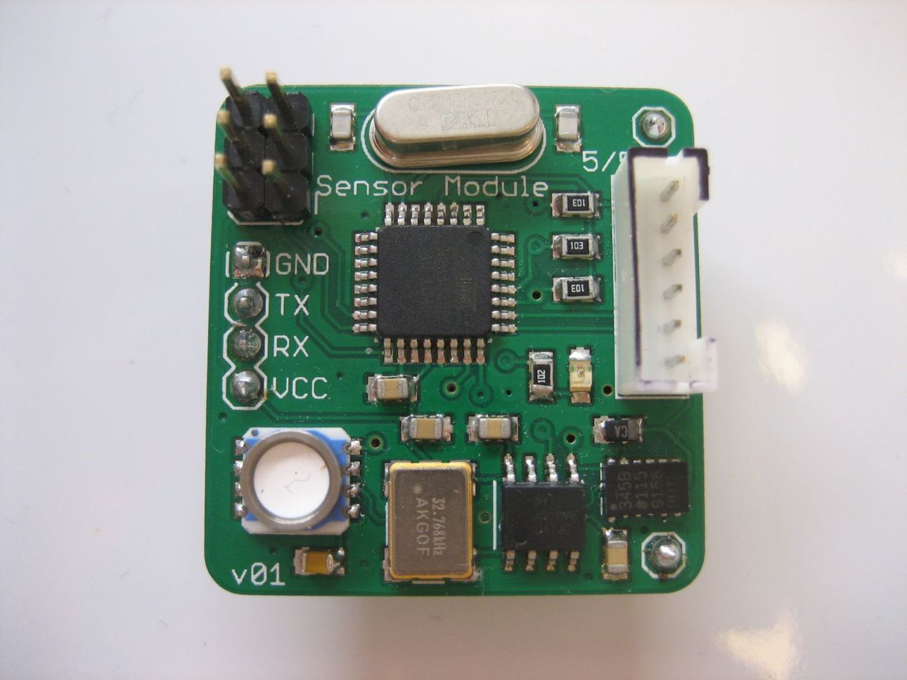
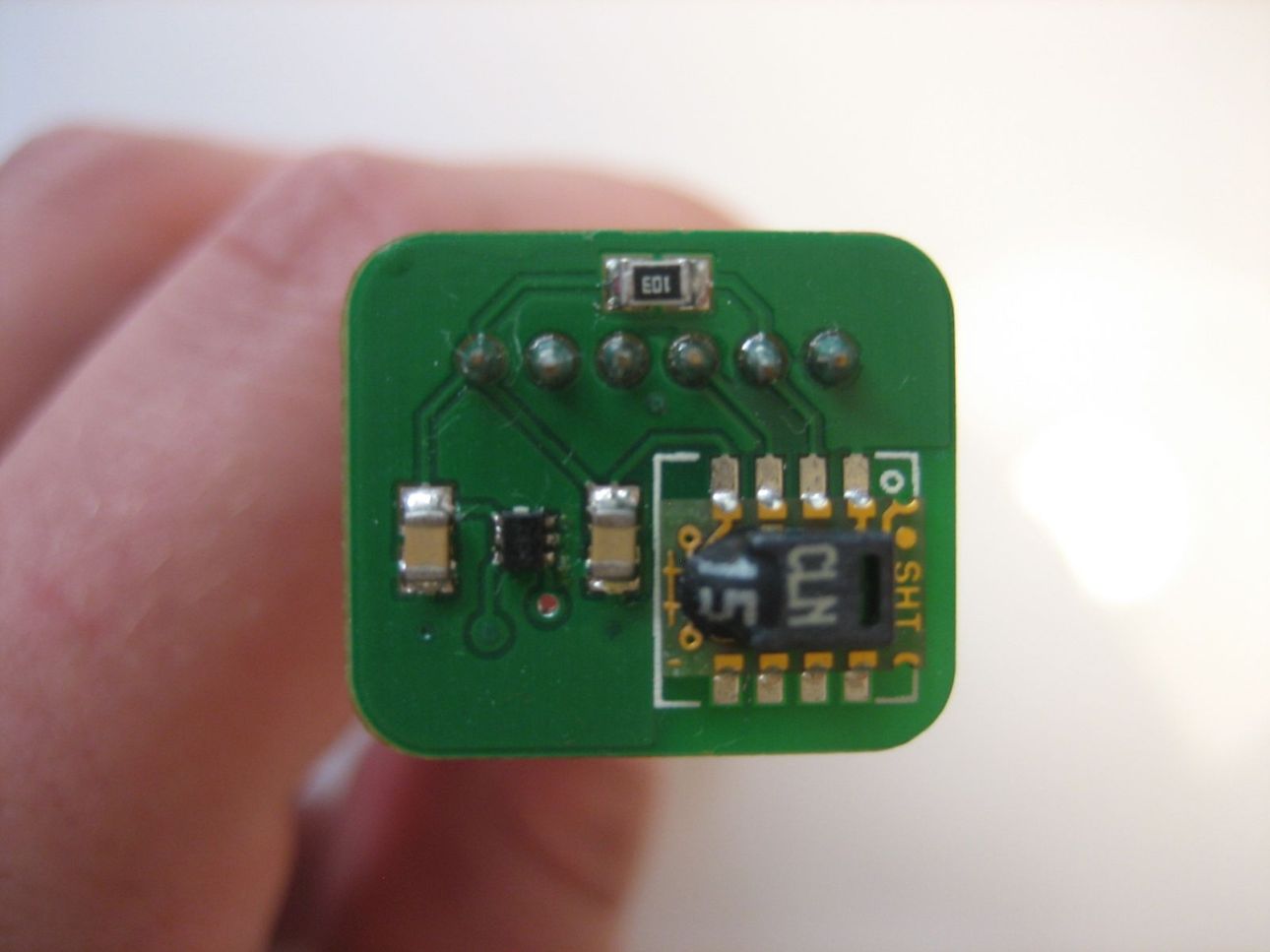
The sensor module consists of a microcontroller and several environmental sensors. This module is dedicated to reading each sensor and sending the data to be logged. It also receives GPS data from the main module and sends it to the data logger. Sensor readings are the only two-way communications on this project. Timeouts on each sensor reading prevent a faulty sensor from locking up the sensor module. Sensor and GPS data is sent to the data logger via serial UART. Just like the main module, the RX line is not connected and the data logger does not respond to any transmissions.
Data Logger Module
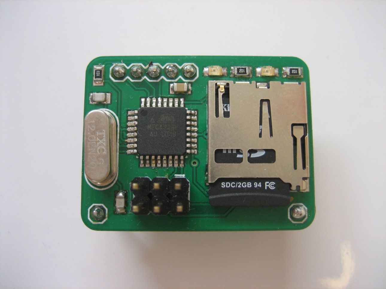
The OpenLog data logger module consists of a microcontroller and a microSD card. The data logger simply listens to the serial UART and writes everything it sees to a text file on the microSD card. All data formatting is done by the sensor module before being sent to the data logger. The data is formatted to the CSV format so it can be easily imported into Excel.


Leave a Reply