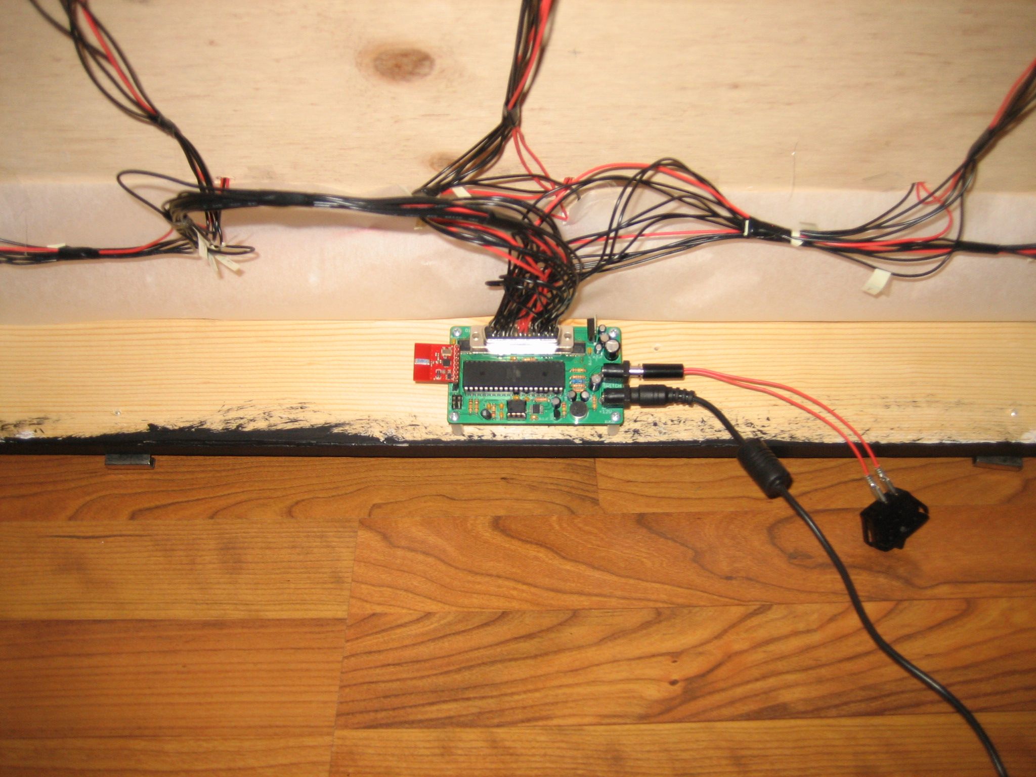

The Disco Table electronics are fairly straightforward. Audio is sampled with a microphone and the volume of the audio is adjusted with a potentiometer. An equalizer display filter detects the peaks of several frequencies of the incoming audio and passes it on to the microcontroller. The microcontroller uses this audio information to update the LED display through the use of two LED drivers. In addition, a handheld wireless remote can control the table and switch what is being displayed. Here is a breakdown of the various electronic components used in the Disco Table.
LEDs
This is the heart of the Disco Table and has a direct impact on the “wow” factor. I decided to follow the black and red theme of the original Daft Punk table by using red super-bright LEDs from Digi-Key. They have a 14,680 mcd rating, which is really bright. They leave a spot in your eyes just like the sun does (try not to do that for too long). They need to show through black tinted glass and a sheet of red acrylic. Two layers of tracing paper were also added during the testing phase to get the light just right, so brighter is always better.
microphone
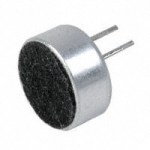
The simplest and most common microphone is the electret condenser mic. A 5V power source and a few external components and it easily interfaces with just about anything. This was the cheapest option for the Disco Table, which doesn’t need crystal clear audio.
Digital Potentiometer
The microphone’s output varies with the volume of the audio it senses. Therefore, I needed a way to control the gain of the audio input so I could scale it depending on the volume of the source. I came across the Maxim MAX5410 Digital Logarithmic Potentiometer. Steady volume control is performed by logarithmically adjusting volume. This has to do with how loud audio seems to the human ear. Digital control makes it easy for the handheld remote to control the gain or for the microcontroller to automatically adjust gain based on the audio input.
Equalizer display filter
The first iteration of the Disco Table had an analog circuit that separated out several frequencies and fed them to individual ADC pins on the microcontroller. The microcontroller sampled them and used the values to drive the display and make things happen. This ended up being very sensitive and more trouble than it was worth. Then I came across the MSI MSGEQ7 seven band graphic equalizer display filter. This chip is perfect and very easy to use. Seven frequencies are peak detected and multiplexed to a single output pin. It runs at 5V and can take a microphone input with only a few components.
LED Driver
NXP Semiconductors offers an extensive line of LED drivers for many applications. I decided on the PCA9622 because it uses the I2C bus and can control 16 individual LEDs at 100 mA each. The high 40V limit allows several LEDs to be connected in series and the 100 mA limit allows several strings of LEDs per output. This is a very flexible chip for what I needed.
wireless receiver
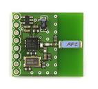
Instead of reinventing the wheel, I found a short-range 2.4GHz transceiver from Nordic Semiconductor called the nRF24L01+. Sparkfun offers a breakout board with the transceiver, external components, and an antenna all-in-one. This made it very easy to just “tack on” wireless capability so I could focus on the actual display portion. It runs off of 3.3V, but has a built-in regulator to step down my 5V supply. I just needed to add female headers to my board to have a place to plug it in.
wireless transmitter
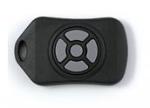
Sparkfun also offers a Nordic Fob battery-powered handheld nRF24L01+ transmitter to match their Nordic breakout board. It has four arrow buttons and a center button. Again, I would rather have an all-in-one solution for the wireless portion, especially to avoid designing a handheld device from scratch. This device simply transmits which button is pressed to the Disco Table to make the table perform actions.
Microcontroller
There wasn’t much to decide on this one. I needed an I2C interface, analog-to-digital converter and plenty of RAM to hold the arrays of patterns. With all power coming from a wall outlet, I didn’t need a low power version or anything fancy. I had a few Atmel ATmega32s lying around so I decided to use one for this project. It runs at 5V and has all necessary hardware interfaces.
Wrap-up
I decided to power the Disco Table from a standard 12V wall power adapter, just like a laptop charger. This is a piece of furniture so it will stay in one place and be in close proximity to a wall outlet. 12V gives me flexibility to string multiple LEDs together and avoid increasing current draw. The next steps are designing the circuit board and building the table.


Leave a Reply