
My LED Bar project uses an Arduino to process button inputs, take analog readings, update the LCD display, and control the LED strips. That’s a lot for a little microcontroller to handle and by the time I had all my features finalized I ran out of pins. All I needed was one more pin for a button input from the control panel. There are many ways to solve this problem depending on your project. However, one of the other buttons was already connected to an analog-to-digital converter (ADC) pin on the Arduino, but only using its digital input functionality. So I came up with a simple circuit to take both button inputs on this pin:
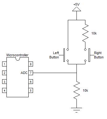
The microcontroller pictured above can be any microcontroller, not just an Arduino. When no buttons are pressed the bottom 10k resistor acts as a pull-down and the microcontroller sees 0V. When the left button is pressed 5V is fed directly into the microcontroller. When the right button is pressed it creates a voltage divider and splits the 5V in half, giving 2.5V. Unfortunately, if both buttons are pressed the top resistor has no voltage across it and it will look like only the left button is pressed. So it’s a good idea to either pick two buttons that are not likely to be pressed at the same time or put the most important button on the left side.
In your Arduino project, just throw an analogRead() command in your main loop and use the result to determine which button is pressed. For the example above, the analog reading will be 0 when no buttons are pressed, 512 for the right button, and 1023 for the left button. These values are spaced far apart, which makes for a very reliable circuit. I used the following ranges in my code to determine which button is pressed:
No buttons pressed: <256
Right button pressed: ≥256 and ≤768
Left button pressed: >768
Analog readings take much longer than a digital input reading, but my project is not time-sensitive and still responds instantly. In fact, I had to put in a timer scheme similar to debouncing a digital button input to prevent multiple hits on a single button press. This circuit isn’t groundbreaking, but hopefully it helps someone out there if they run out of Arduino pins.
Adding More Buttons
The following circuit expands the first example to 4 buttons. You can expand even further, but eventually you’ll hit a limit where temperature variations and resistor tolerances will cause unreliable readings.
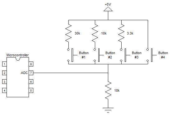
The ADC readings for the above circuit are as follows:
None: 0 (0V)
Button #1: 256 (1.25V)
Button #2: 512 (2.5V)
Button #3: 770 (3.76V)
Button #4: 1023 (5V)
Simultaneous Button Presses
The following circuit expands the first example to add the ability to detect when both buttons are being pressed. The tradeoff is that the ADC values are closer together, but this shouldn’t cause problems.
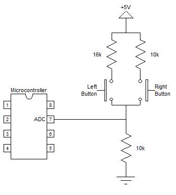
The ADC readings for the above circuit are as follows:
None: 0 (0V)
Left Button: 394 (1.92V)
Right Button: 512 (2.5V)
Both Buttons: 634 (3.1V)
Wrap-Up
As you can see, there are many ways to hook up multiple buttons to a single ADC pin. There are many other methods as well. For instance, you could use the internal pull-up resistor instead of the 10k pull-down resistor I used in my examples. The resistors could also be in series for each button so that different buttons engage different numbers of resistors, creating the effect of adding resistance. Experiment and search around online to find the best solution for your project.


Leave a Reply