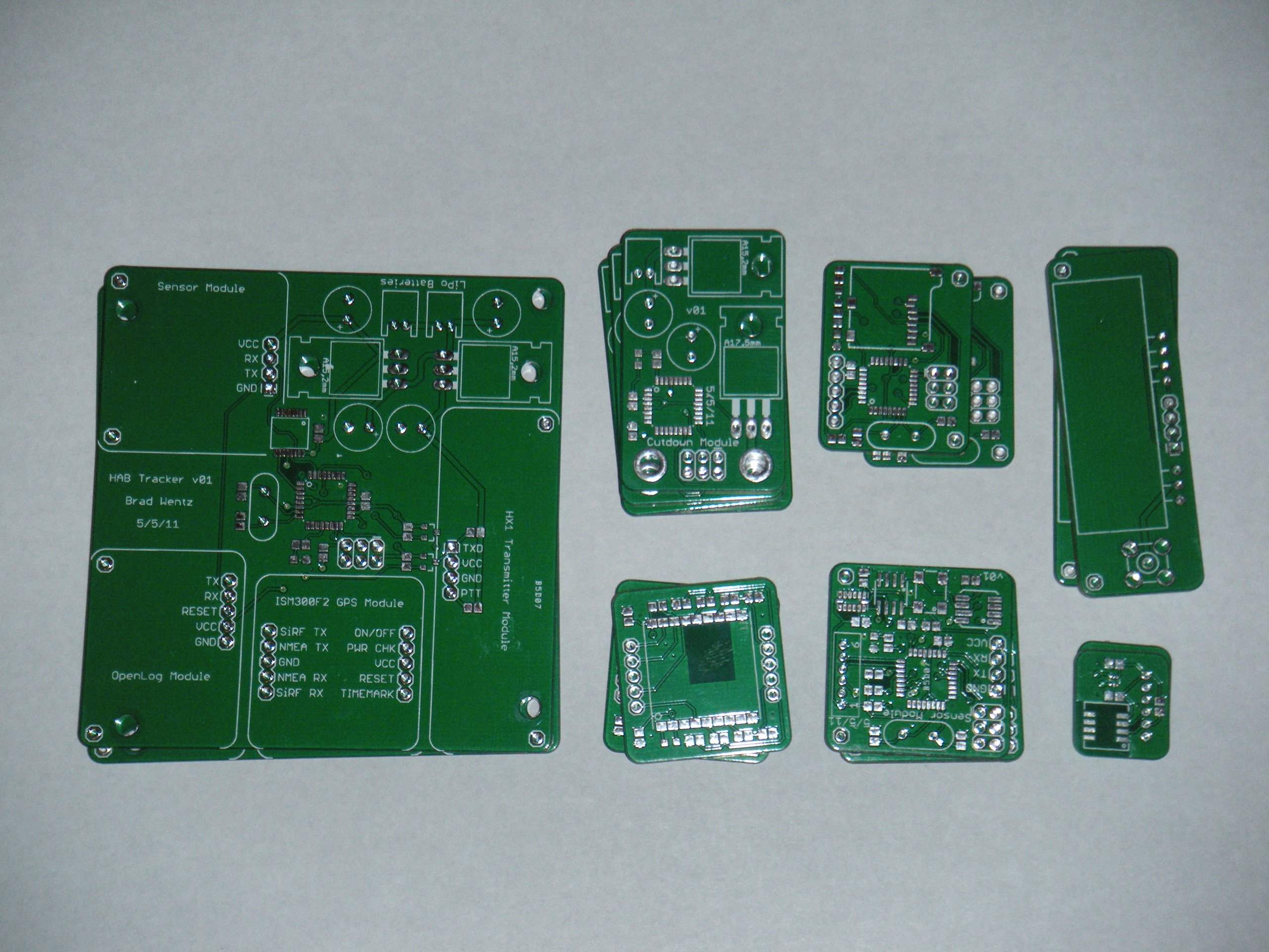

The physical components of a high altitude balloon are fairly simple. The balloon lifts, the parachute brakes, and the capsule holds on for dear life. The electronics for tracking the balloon are by far the most important aspect of a near spacecraft. As I mentioned in my last post, GPS and a radio transmitter are absolutely necessary and should be carefully selected. I decided early on that I also wanted to measure the environmental conditions that the payload experiences as it journeys to the stratosphere and back. Here are the various electronic components and sensors I selected and the reasons behind my choices.
GPS

There are many choices when selecting a GPS receiver. It’s important to note that there are limitations set on civilian GPS units that apply to high altitude balloons. Civilian GPS units are not allowed to travel above an altitude of 11 miles AND at speeds faster than 1670 fps. This is to prevent them from being used for missile guidance. Unfortunately some GPS manufacturers incorrectly place an OR in that logic statement, which makes the GPS stop reporting positions above 11 miles even at speeds lower than 1670 fps. Most GPS datasheets do not mention if this incorrect limitation applies.
After a bit of searching I found the Inventek ISM300F2-C5-V0004 GPS module. Version V0004 has firmware for high altitude applications with a ceiling of 137,795 ft. It runs at 3.3V and works at cold temperatures for balloon applications. A standard serial UART is all that is needed to interface with this chip. Only 25mA is required while in tracking mode. They also sell an active antenna (ACTPAT254-01-IP) that plugs right into the IPEX connector located on the chip itself.
Radio
High altitude ballooning was basically pioneered by amateur radio operators. Most of the HAB projects use some sort of handheld radio operating on the amateur radio bands. However, I didn’t have my ham license so I started to pursue the Digi XTend 900MHz modules. They offer a 40 mile range and 1 Watt power output, but they cost about $185 a piece. I would need two, one on the balloon and one on the ground for tracking. That’s way too expensive.
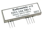
I started looking at ham equipment again and found the Radiometrix HX1 300mW Transmitter. They have a great range and are pretty cheap (about $40). Using the ham frequencies also means you have a high likelihood that a digipeater will pick up your transmission and rebroadcast it so your signal travels farther (sometimes up to 400 miles!). Some digipeaters will also “igate” your transmissions, which means the information is put on the internet so you can track it from any computer in real-time.
The only drawback to this transmitter is that it requires 5V. A simple fix is to have two power rails, 3.3V and 5V. This requires another battery, but doesn’t add much to the cost or complexity. Two LiPo batteries in series will do the trick as explained in the battery section below.
Temperature Sensor
The Texas Instruments TMP102 temperature sensor measures from -67 °F to 302 °F. It operates at 3.3V and uses the I2C protocol. Therefore, it doesn’t require an ADC and it can be stacked on the I2C bus with other sensors. This is a simple sensor and an easy choice.
Humidity Sensor
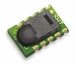
The Sensirion SHT15 humidity sensor measures from 0 to 100% relative humidity. It also measures temperature to calibrate the humidity reading, but this can also be compared with the dedicated temperature sensor. Temperature readings are from -40 °F to 254 °F. This sensor runs at 3.3V and uses a proprietary two-wire interface similar to I2C. It will be very interesting to see how humidity changes with altitude.
Pressure Sensor
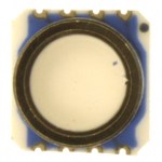
I chose the Intersema MS5540C barometer module to measure absolute pressure. The pressure range is from 10 mbar to 1100 mbar, which should cover the range of pressures experienced during the flight. It also measures temperature to calibrate the pressure reading. Temperature readings are from -40 degrees F to 185 degrees F. This chip runs at 3.3V and is interfaced using the 3-wire SPI protocol. Pressure can be used to calculate altitude, so this measurement can be compared with the GPS altitude reading.
Accelerometer
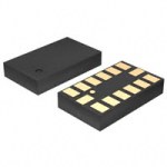
Analog Devices offers the ADXL345 3-axis accelerometer. It can measure forces up to 16 g, which should be way more than the payload will experience. This chip runs at 3.3V and uses the I2C protocol. I expect the balloon burst and high speed descent to show some pretty violent readings.
Magnetometer
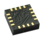
I had originally planned to include a magnetometer (digital compass sensor) to detect which way the payload is facing and how much it spins. I decided to scrap this at the last minute, but I was going to use Honeywell’s HMC5883L. It runs at 3.3V, uses the I2C protocol, and can measure in all three axes.
Data Logger
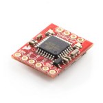
I don’t want to transmit all of the sensor readings because I want to conserve power and keep the radio usage limited to position data. Therefore, I needed a way to store the sensor (and GPS) data for later retrieval. The OpenLog data logger is an open source project started by Sparkfun. It takes any information received on the serial port and stores it to a microSD card. I incorporated the OpenLog hardware into my circuit boards instead of purchasing a stand-alone module.
Microcontroller
I am very familiar with Atmel microcontrollers so this narrowed down my search pretty quickly. They are very reliable and I already have the necessary programming tools. I chose the ATmega328P because it has plenty of storage space, runs at 3.3V and offers all of the hardware interfaces I need for the various sensor interface protocols. I will use one microcontroller to handle the GPS and radio and another to take sensor readings. The position data is more important, so this will provide separation and prevent a bug in the sensor code from interfering with position reporting. The OpenLog module also uses this chip.
Batteries
Batteries are the last thing to decide on after the main components are selected. All of the parts selected run off 3.3V, with the exception of the radio transmitter, which runs at 5V. Lithium Polymer rechargeable batteries run at a nominal 3.7V. Two of them in series will produce plenty of voltage. I used two low-dropout regulators to create 3.3V and 5V supplies.
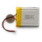
Flight and recovery times can last for several hours so power conservation and adequate batteries are very important. If the payload lands in a ditch and the radio signals are mostly blocked, then you’ll be glad the batteries last longer than the flight so you have time to drive to the last known location to re-establish contact. I added up all of the worst-case current draws for each component (totaling 200 mA) and assumed they drew that much for a 5-hour flight. That means I would need batteries with a 1000 mAh capacity, but then I doubled that just to be sure. This is overkill, but I really don’t want to lose several hundred dollars worth of equipment just because the batteries ran out. I chose 2000mAh LiPo batteries from Sparkfun.
Wrap-Up
All of the sensors take readings very rapidly and will allow me to get a good picture of how the environment changes as the balloon travels through the atmosphere. I will put the accelerometer and barometer inside the capsule (the barometer will also give me internal temperature). The capsule will not be perfectly sealed so the pressure reading will match the external pressure. The temperature and humidity sensors will be located on the outside of the capsule to get external temperature and more quickly react to changing humidity.


Leave a Reply