
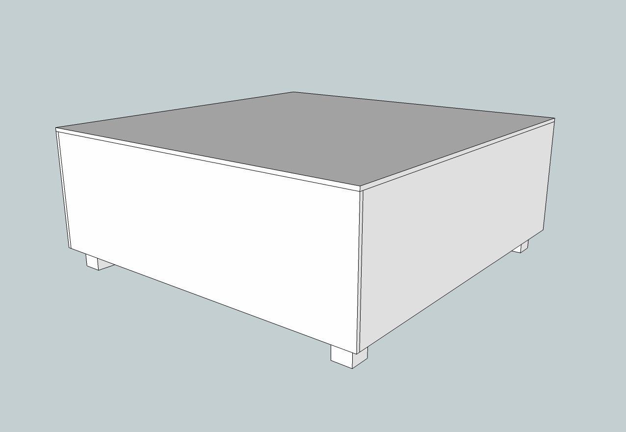
I spent a lot of time designing the Disco Table before I stepped foot in a hardware store. The first step I took was laying masking tape on my living room floor to get an idea of how big the table should be. Six-inch squares, the dividers, outside walls, and glass came up to about 36 inches on each side, or three feet. That seemed like a good number to shoot for when I saw it outlined on my carpet. I used an existing coffee table to get an idea of the height.
Then I used Google SketchUp to design the table in 3D. SketchUp is a great way to see how everything fits together. The actual woodwork was very simple, but the light cube dividers had to fit together perfectly to stop light from leaking into the neighboring cubes. With SketchUp you can just throw a design together and then use the ruler tool to get dimensions of the pieces when it’s time to head to the hardware store. Here’s the SketchUp model I came up with for my design.
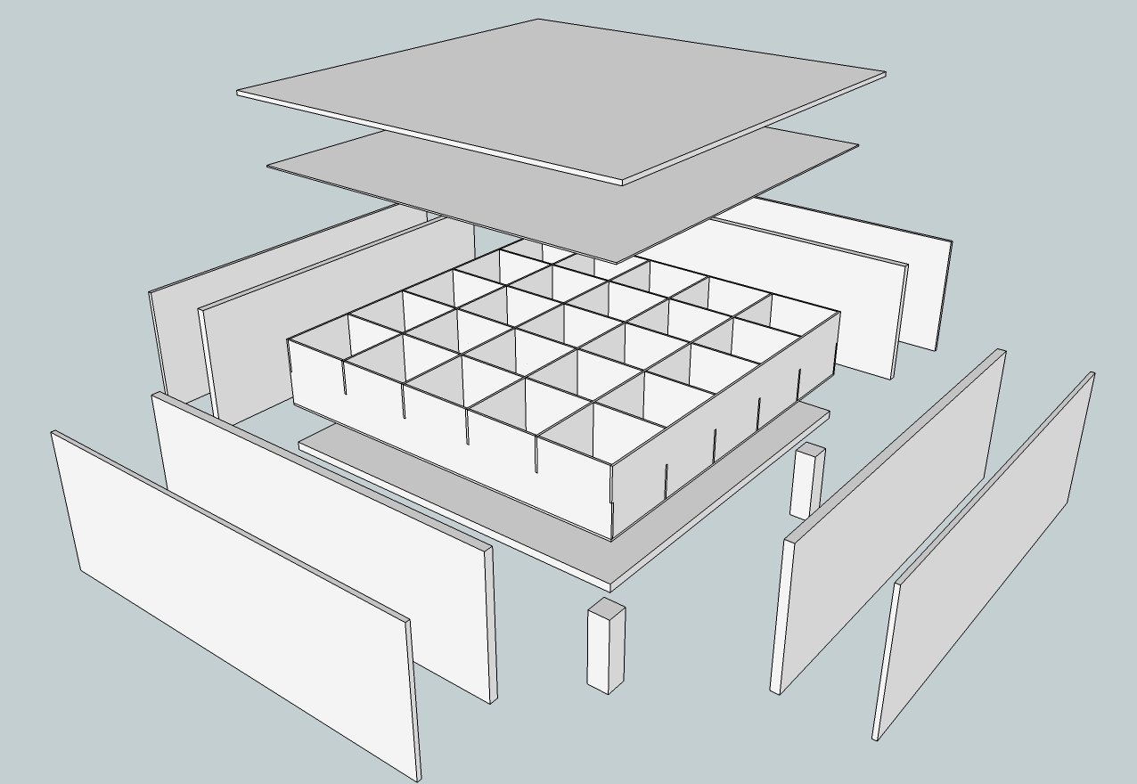
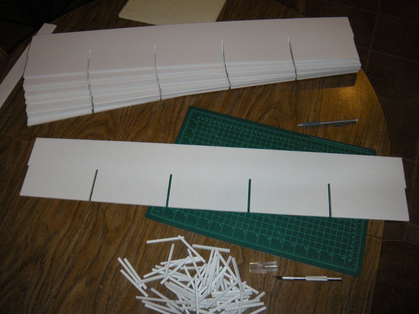
The light cube dividers were cut from sheets of foam board from a local hobby store. The great thing about this design is that all of the dividers are exactly the same. All six in one direction are face-up and the other six are face-down. They interlock to form a strong grid that is set into the wooden frame of the table.
The wooden side pieces were cut from 1″ pine, which is very lightweight. The bottom slab of the table, which only has to support the grid of light cubes, was cut from 3/4″ plywood. The legs were cut from a section of 4×4 fence post. I built the entire wooden frame upside down on a hard, level floor. This ensured the top of the table was straight and level, which is important when a 3’x3′ piece of glass is going to rest on it. I cut the sides and placed them around the light cube grid before screwing them together to ensure a tight fit. Then I secured the bottom section of plywood to the sides. Finally, the legs were put into place and screwed to the sides and bottom. This table can definitely handle the weight of 5 big pieces of glass and whatever gets set on it, yet it can be moved by one person if the glass is removed.
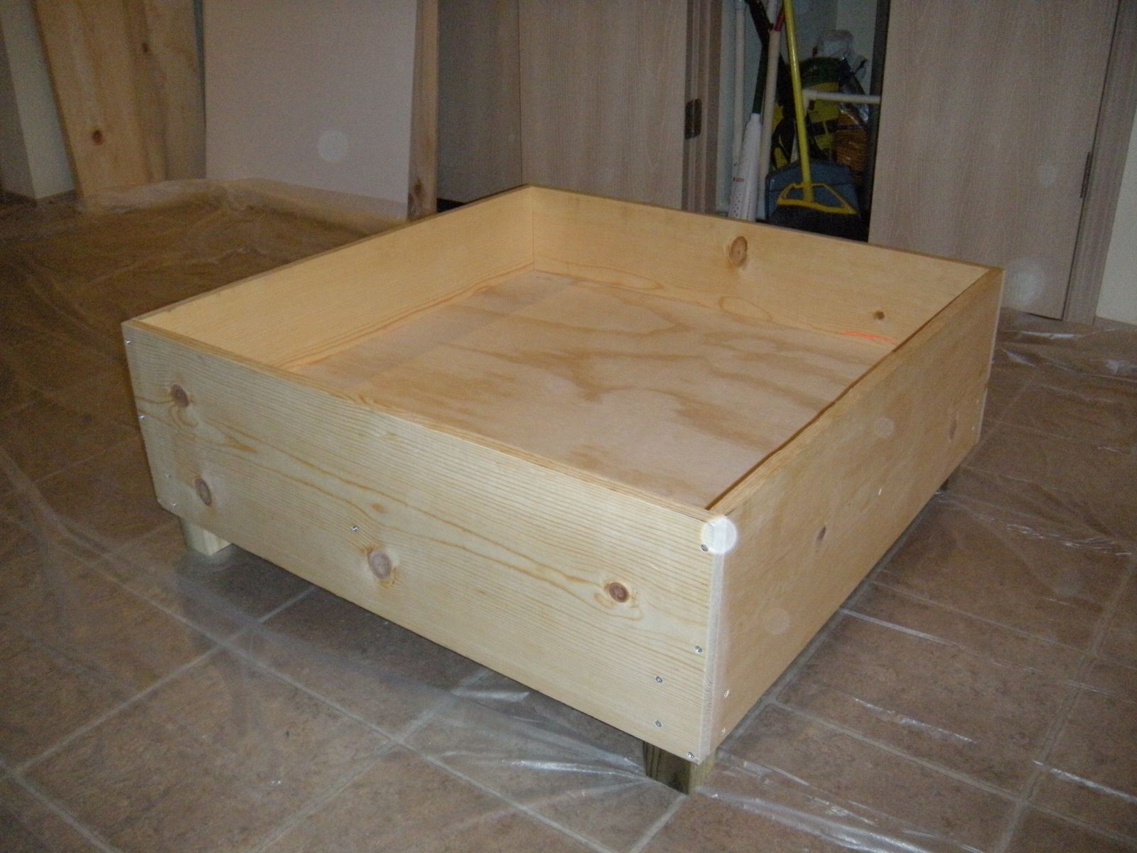
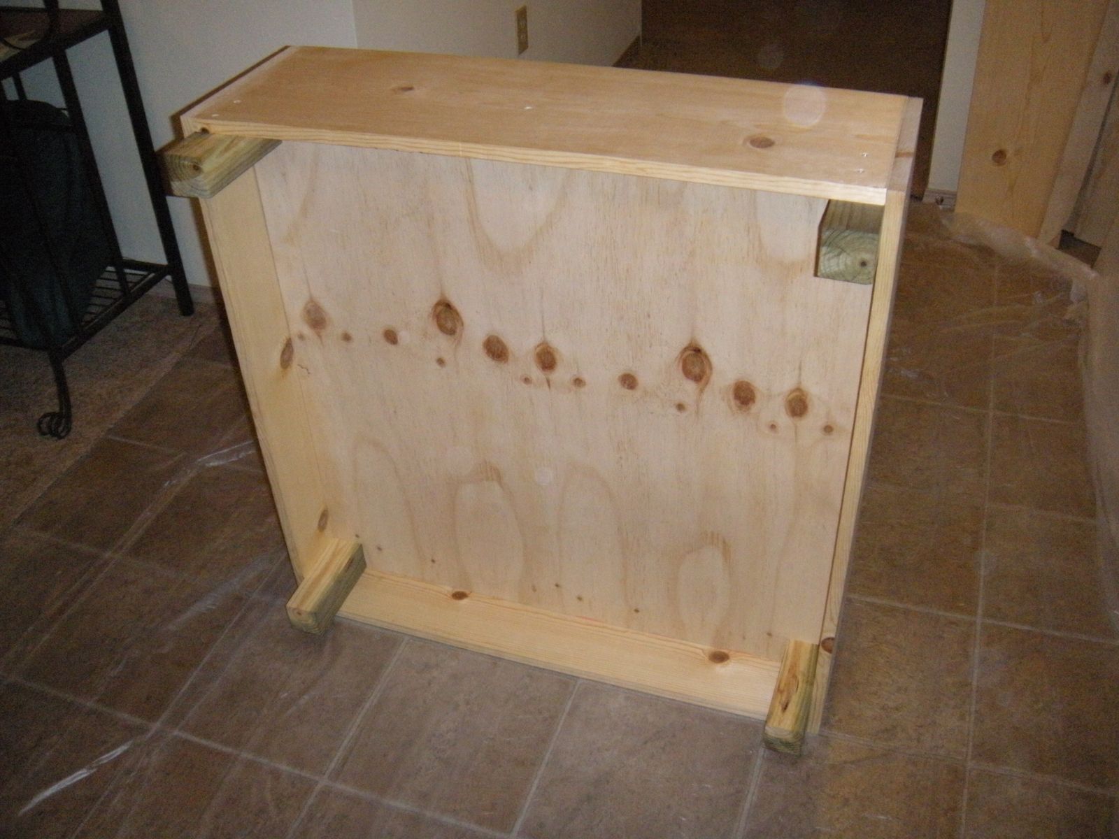
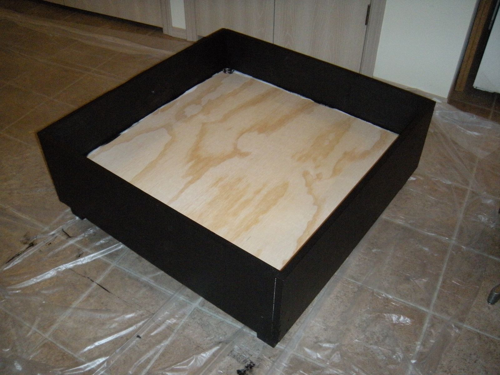
I painted all of the visible parts with several coats of primer and black latex paint.
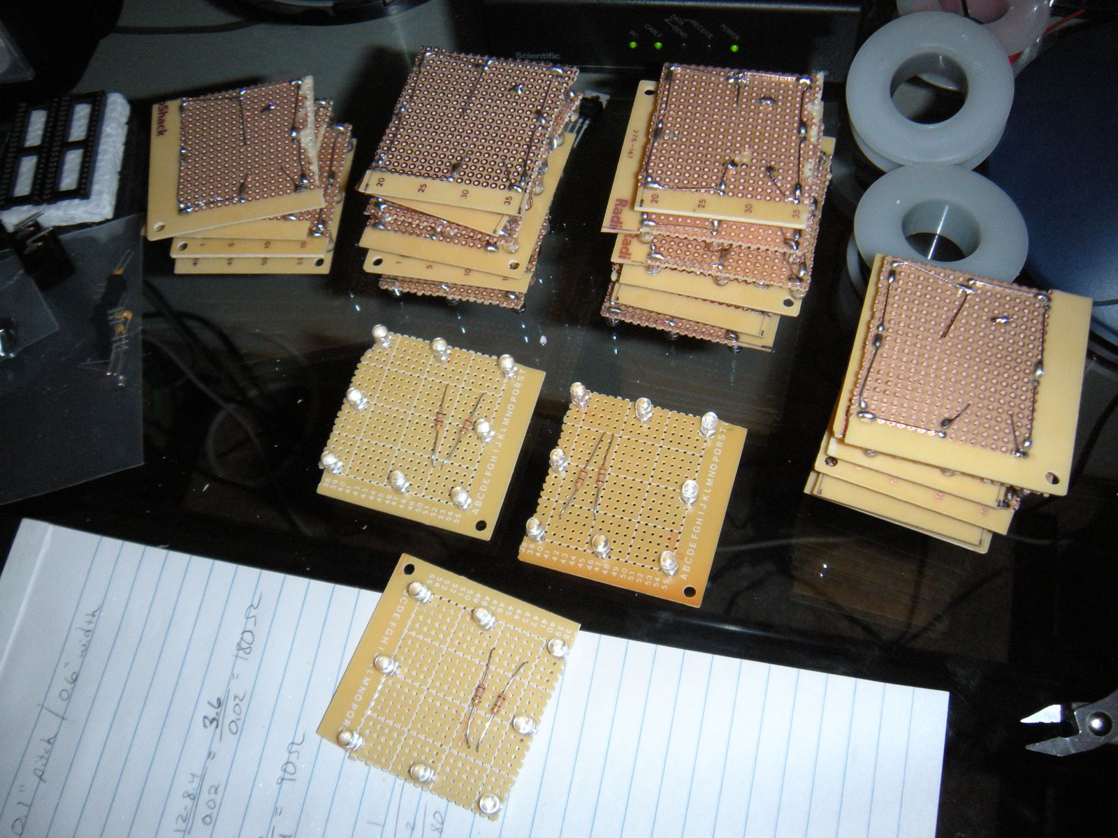
I started assembling the LED boards that illuminate each cube while waiting for each coat of paint to dry. There are two strings of 4 LEDs in each of the 25 cubes, so there are 200 LEDs on the top of the table! To make things simple I bought a few prototyping boards from Radio Shack and cut them into smaller squares. I bent the LED and resistor leads in such a way that I didn’t need wires.
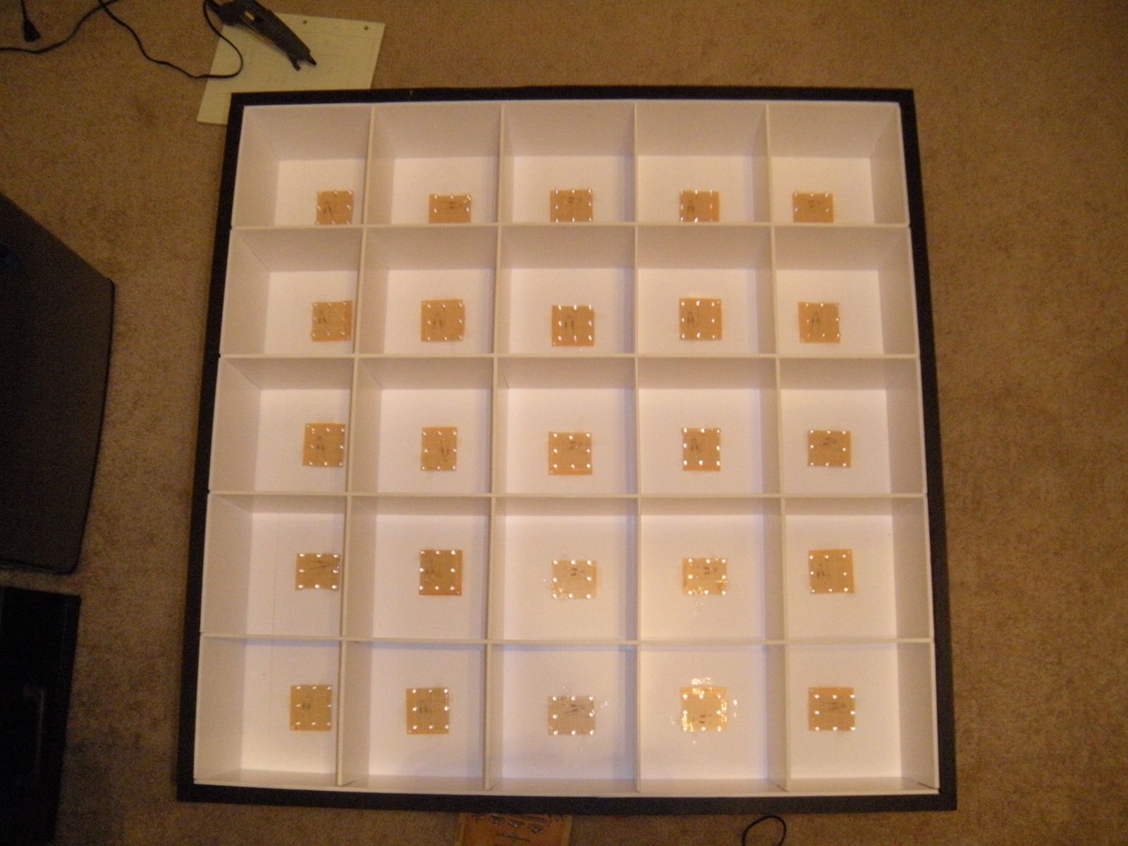
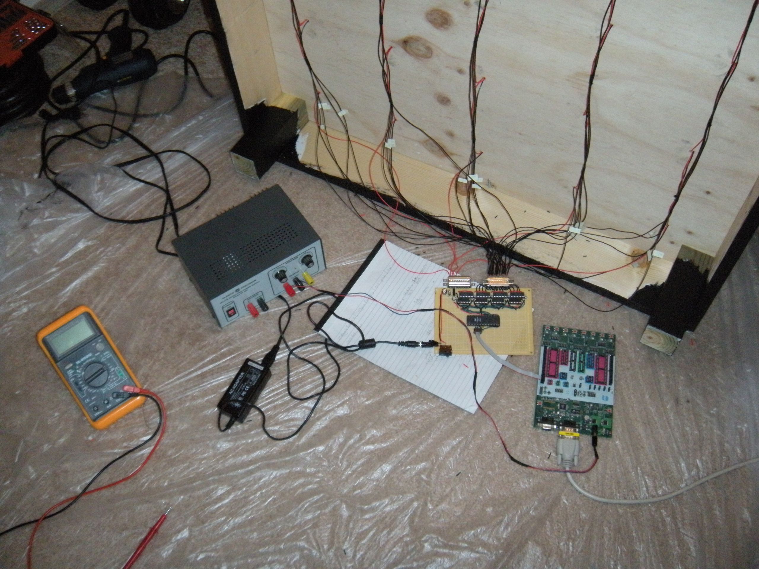
Then I drilled holes in the bottom of each cube for wires to come through, cut wires and taped them in position, and soldered everything together. The LED strips were created by sticking LEDs into pieces of foam board and connecting them together with wire. All of the power and ground wires are connected to a single 44-pin D-Sub connector where the circuit board will be installed.
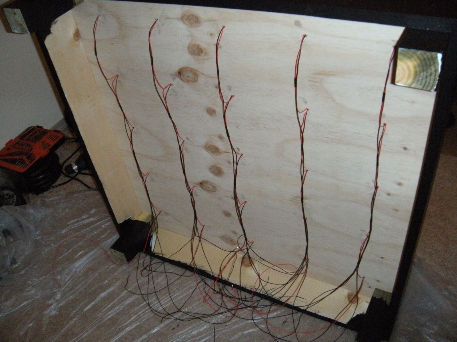
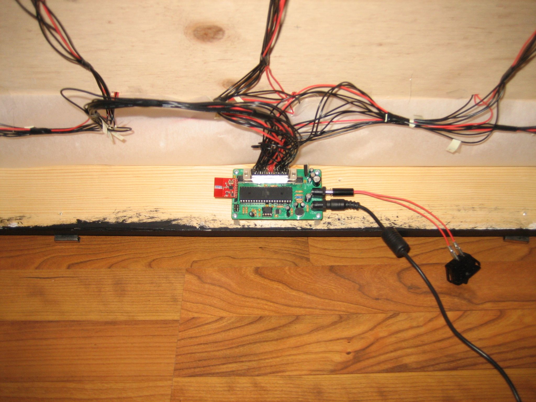
The pieces of black glass were ordered from a local glass shop and the red acrylic was ordered online. I lined the entire top of the table with 1/2″ weatherstripping for the large glass top to sit on. This cushions the glass and keeps it from sliding around. I screwed 4 metal bathroom mirror holders on each side of the table for the side glass. They slide up and down to release the glass, making it easy to break down for transporting.
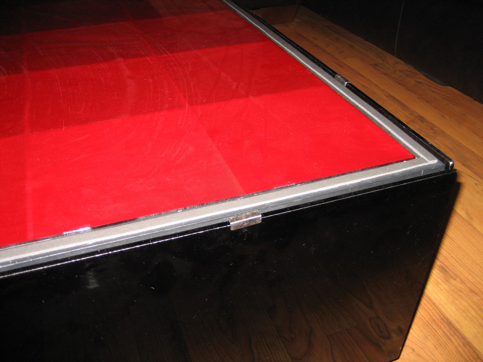
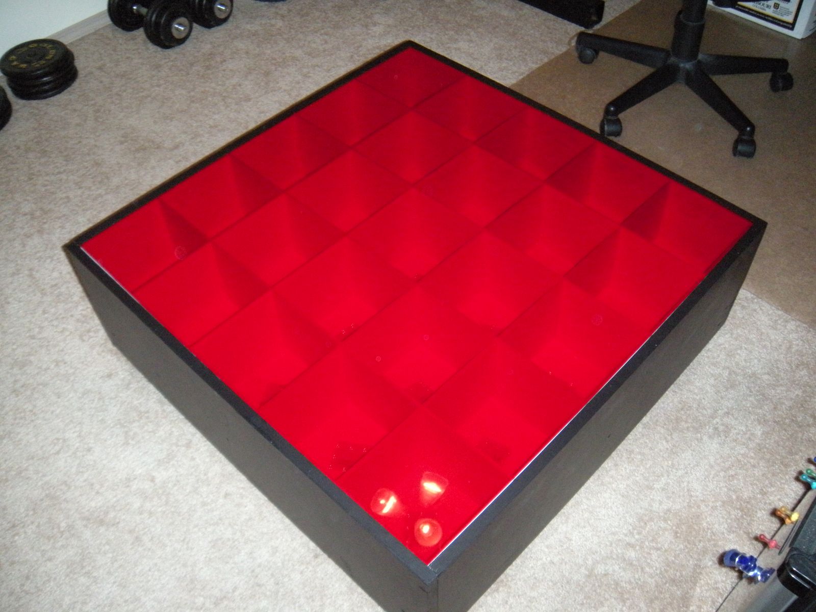
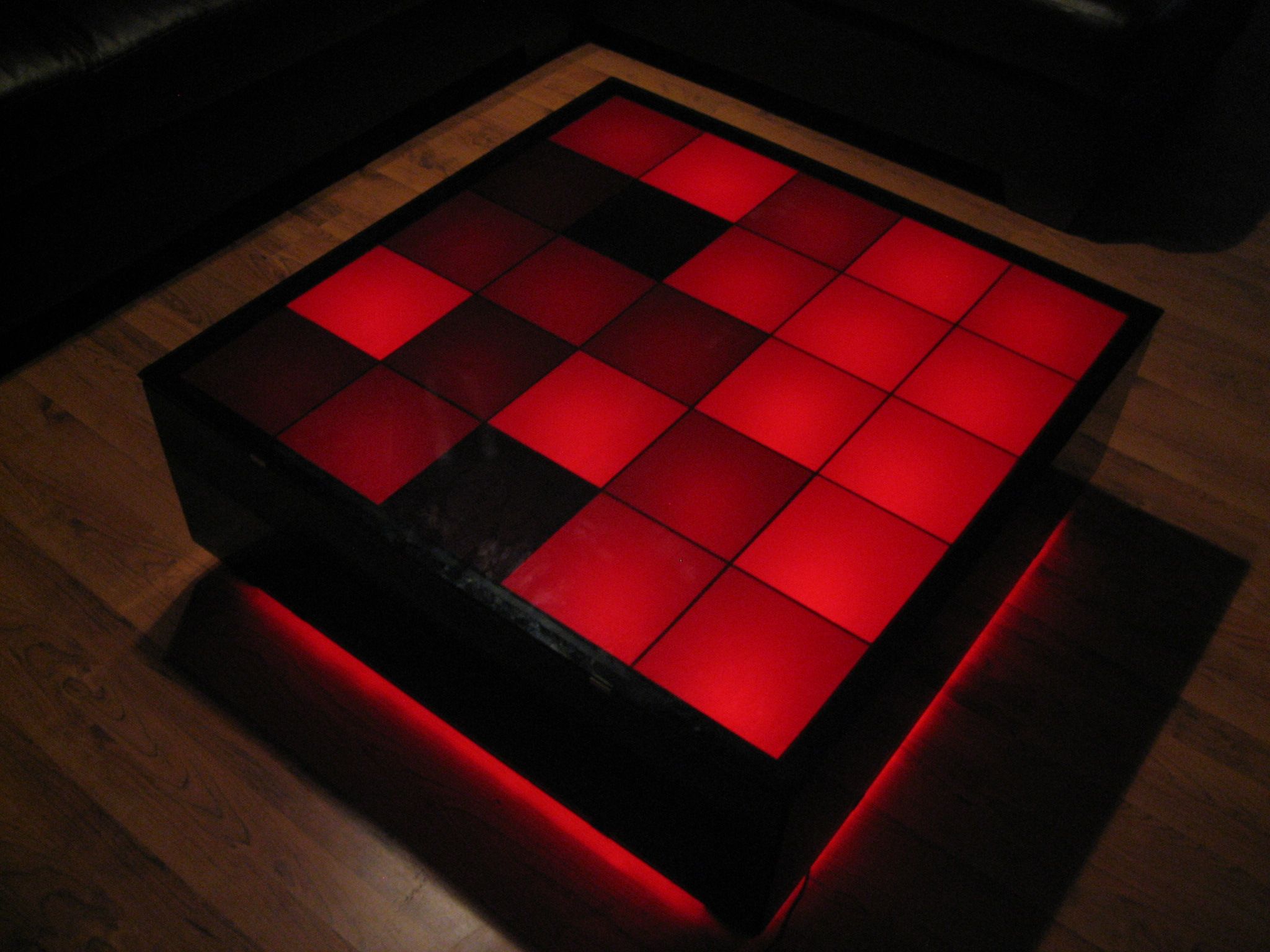
The LEDs are very bright and are clearly visible through the black glass and red acrylic. I wanted them to be invisible and create a glowing effect. I purchased a large roll of tracing paper from Amazon and taped a piece of it to the sheet of red acrylic. This spread the light out a bit and hid the inside of the cubes.
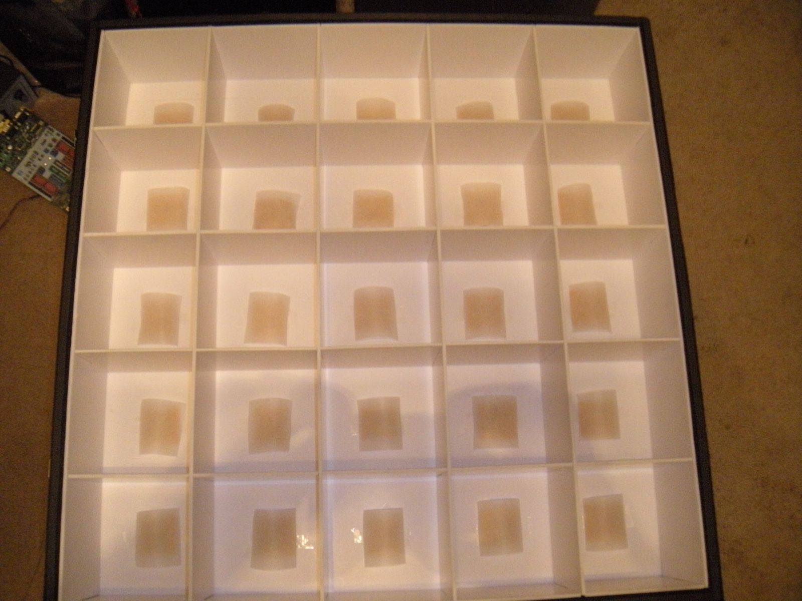
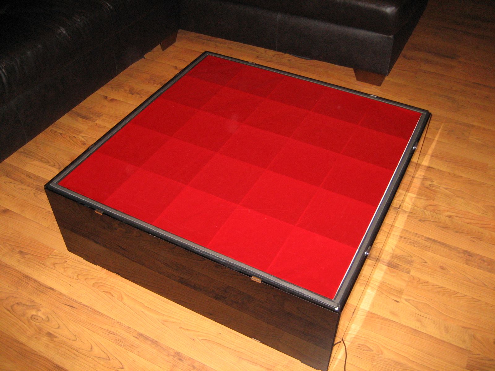
It still left a focused spot of light in each square. Then I cut little strips of tracing paper and looped them over the LED boards. This diffused the light enough to create an even glow across each of the squares. I looped long strips of tracing paper over the LED strips on the bottom of the table to create the same effect on the floor. Here is the final product. The picture on the right was taken while the table randomly turned on squares to different brightnesses.
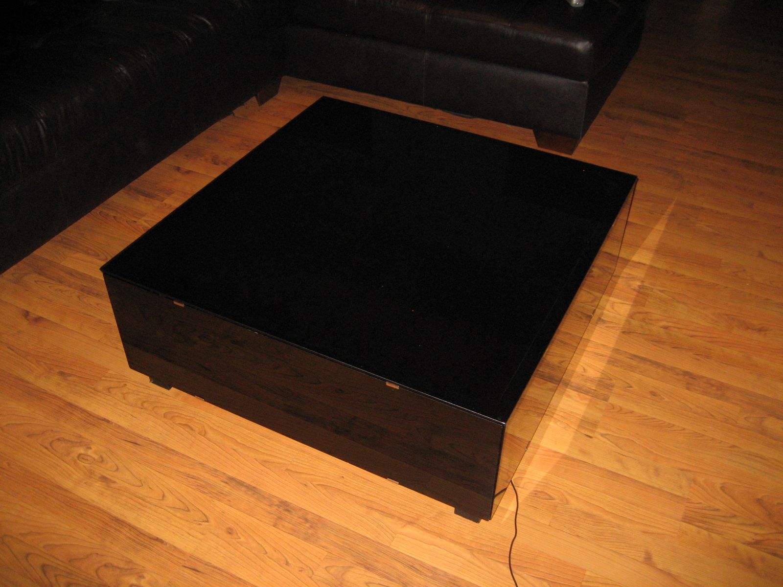
Check out some videos of the disco table in action.


Leave a Reply