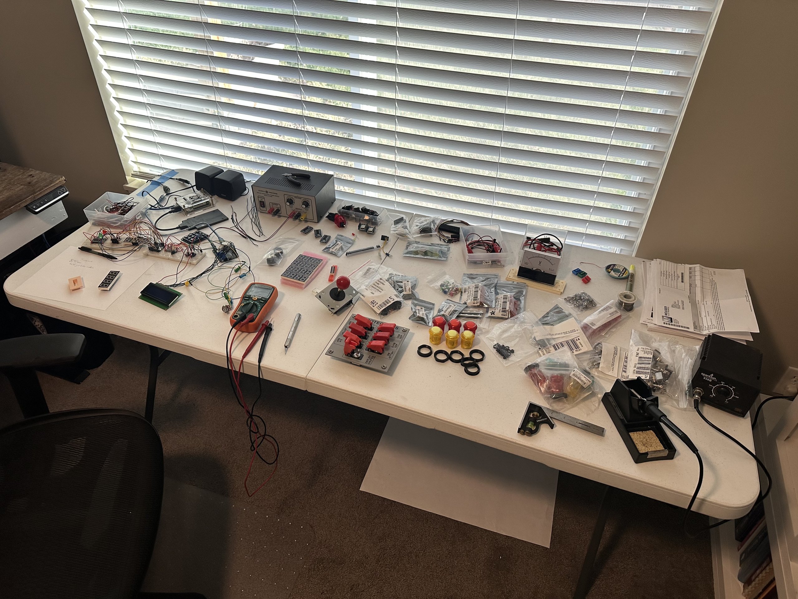

I spent some time researching the Apollo 11 mission and came up with a full list of activities that the simulation should include. They cover everything from initial launch preparation to splashdown in the Pacific. From there I was able to map out most of the switches and indicators that are needed to execute the full mission. They will likely change, but that’s how these things go.
I figure I need to read 62 digital and 4 analog inputs, write to an LCD character display, and drive roughly 620 LEDs!
The first decision is the brain for the simulation itself. I happened to have an old Raspberry Pi 3B+ lying around from an old project. It will act as the higher-level controller for the simulator by managing the mission sequence, audio, timing, and other logic.
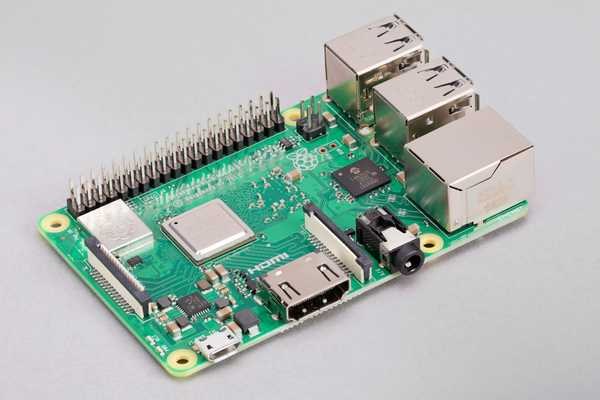
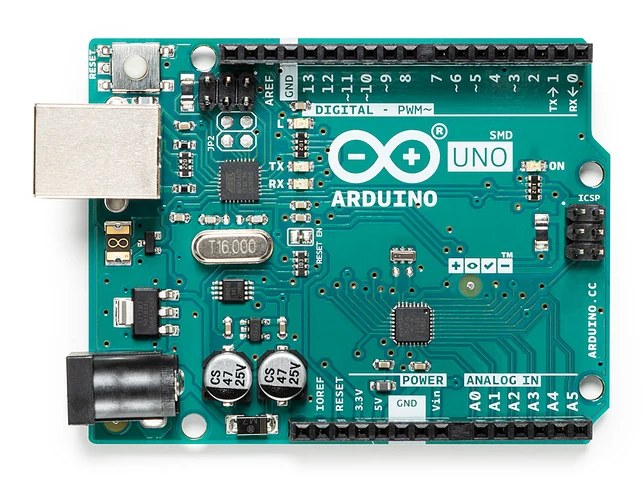
I don’t have much confidence in an old Pi handling low-level device I/O while running a full simulation, playing audio, and other tasks at the same time. So, I decided to use a separate Arduino Uno to handle all of the panel I/O. It will read switches, buttons, potentiometers, a joystick, and keypad, then control various lights and displays. The basic idea is that the Pi knows where the spacecraft is in the mission, while the Arduino takes care of interacting with all of the switches, lights, and displays.
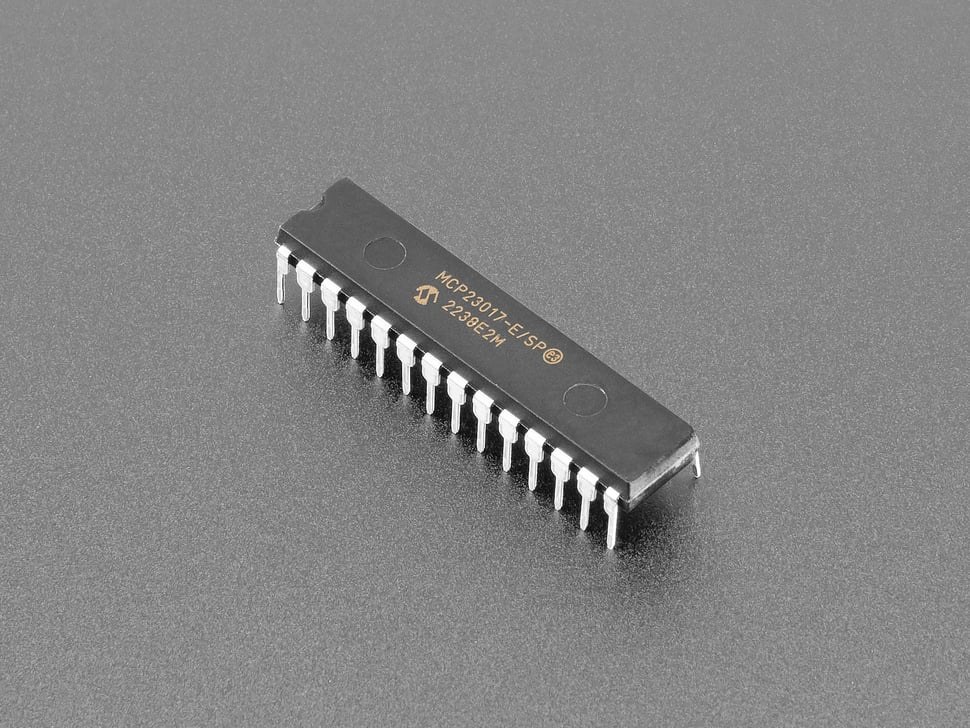
Since there are far more devices than a single Arduino has pins for, I’m using I/O expanders to add a large number of additional digital inputs and outputs over a small number of pins. The MCP23017 has 16 I/O pins, has been around forever, and works on the I2C bus so only two wires are needed to communicate with it. I’m using 4 of these for a total of 64 inputs.
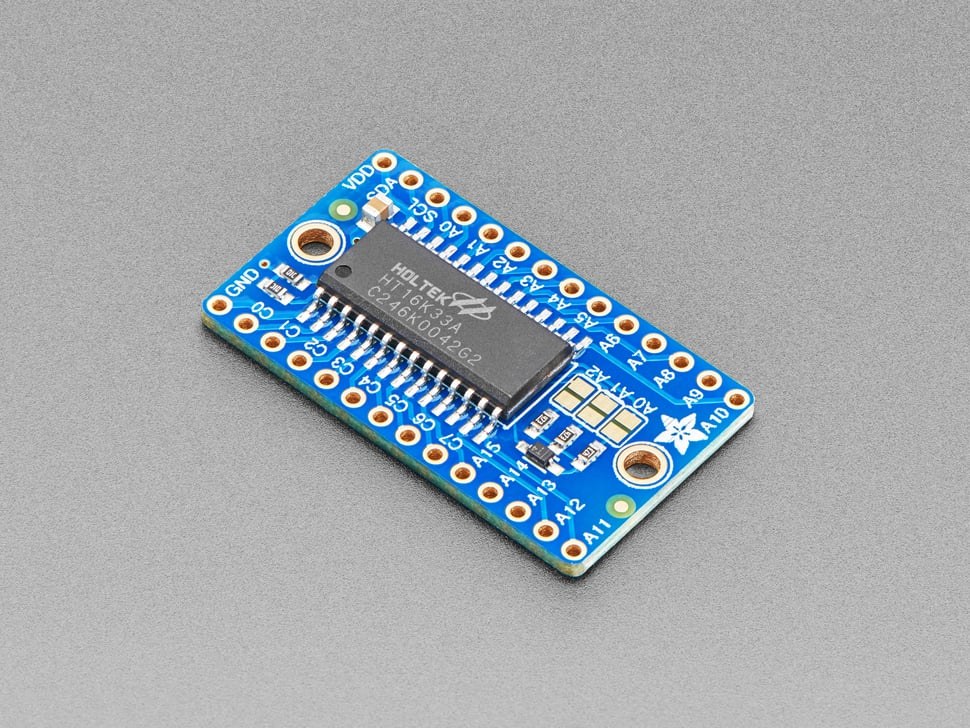
Sticking with the I2C bus as my main communication path, I decided to use LED driver boards to allow the Arduino to handle hundreds of LEDs. The HT16K33 LED matrix driver boards can handle 128 LEDs if they’re wired in a matrix configuration and they handle the repetitive switching and multiplexing needed to keep large groups of LEDs and displays updated. I’m using 6 of these for a total of 768 possible LEDs.
That covers most of the main electronics on the simulator. There are a few other devices to call out specifically since they help create the look I was going for.
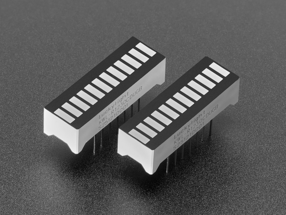
There are many levels on a ship that need to be monitored: fuel, batteries, voltage, current, power, etc. These Luckylight 12-segment LED bar graphs are perfect for this. They have a red and green LED in each segment that when lit up together create orange. Three colors to show good, warning, and alert. That makes 24 LEDs per bar graph, but they’re already wired internally in a matrix.
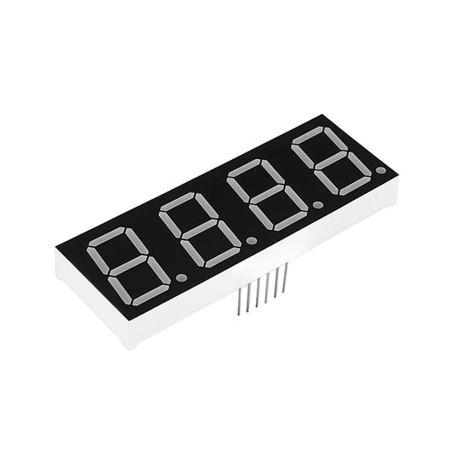
A 1960s spaceship needs plenty of 7-segment displays to show the mission timer, attitude, and other critical values to the astronauts. These 4-digit displays are packaged nicely and I can just hide a digit behind the panel for displays that only need 3 digits. Each digit and associated decimal point is made up of 8 LEDs, but the entire device is already wired in a matrix to reduce pin counts.
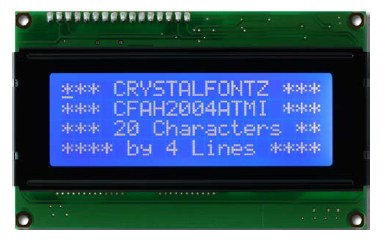
I needed a way to give the astronauts messages from Houston or the ship’s computer that would stay up even after voice audio plays. I re-used the 4×20 LCD character display from my LED Bar project. It doesn’t use I2C, but I have plenty of Arduino pins available to handle this.
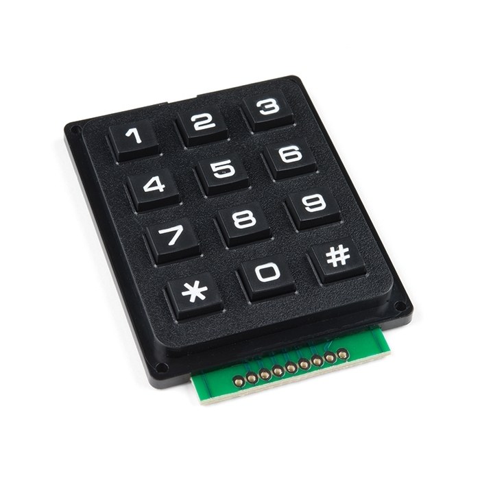
One of my goals was to include math problems in this project for my kids to solve. So, I needed a keypad for them to input numbers. This keypad doesn’t use I2C and requires scanning the keys since they are matrixed together, so it has to be handled differently than the other inputs.
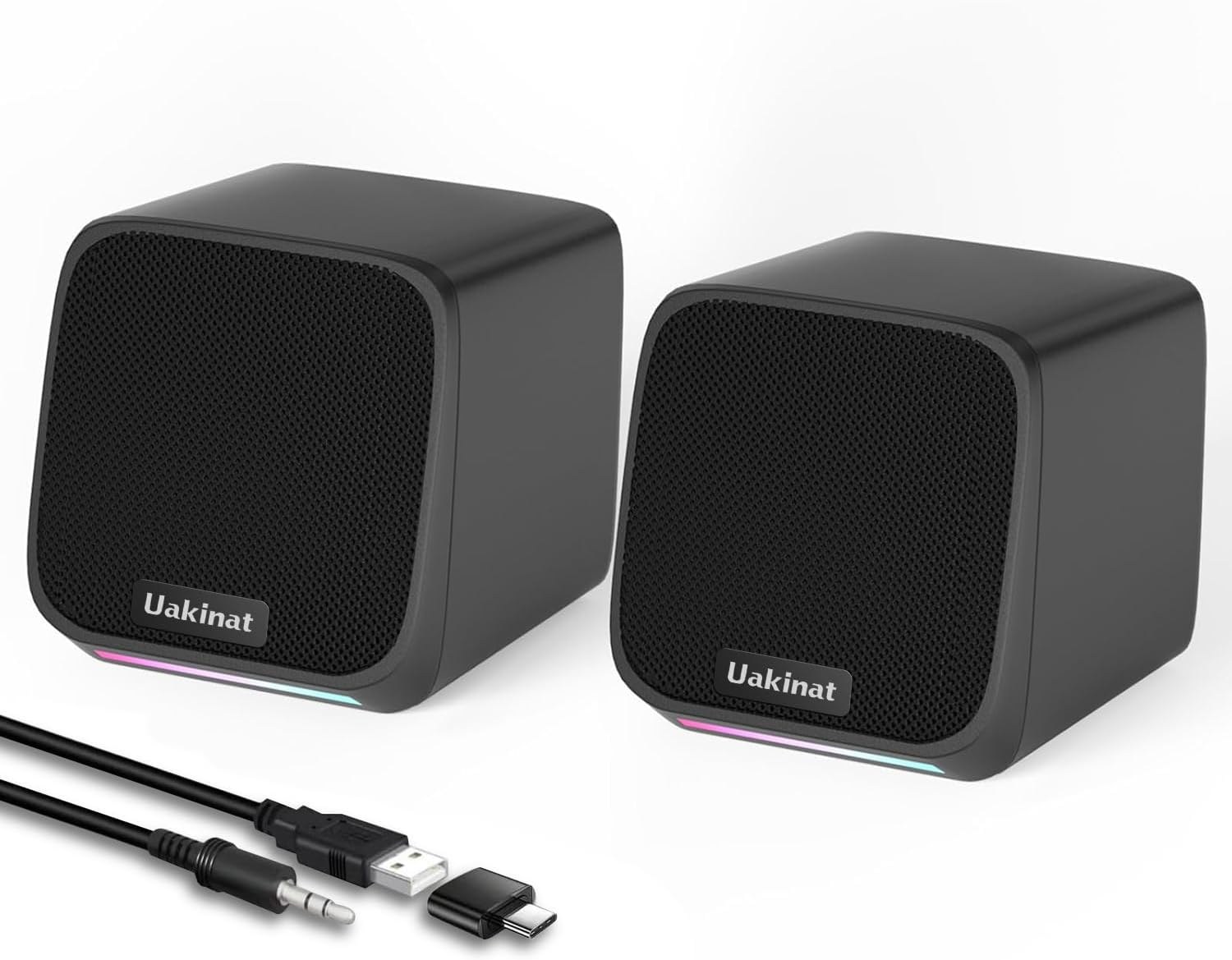
Finally, I needed speakers to make the experience fully immersive. I found a cheap pair of external speakers that could fit on two separate panels. They plug into the Pi’s standard audio jack and get external power from the Pi’s USB port.
The rest of the components include several types of toggle and rocker switches, illuminated pushbuttons, red and green indicator LEDs, potentiometers, and a joystick. My full list of components is shown below with links to where I bought them.
The next step is figuring out how to divide everything into logical panels and how all of it will be wired together.
Parts List
| Source | Part # | Description |
|---|---|---|
| Adafruit | 1427 | 16×8 LED Matrix Driver |
| Adafruit | 732 | 16 I/O Port Expander |
| SparkFun | COM-11405 | 7-Segment Display |
| Adafruit | 1719 | 12-LED Bargraph |
| Adafruit | 3487 | Green Arcade Button |
| Adafruit | 3489 | Red Arcade Button |
| Adafruit | 3488 | Yellow Arcade Button |
| SparkFun | COM-09182 | Arcade Joystick |
| SparkFun | COM-14662 | 12-Button Keypad |
| Adafruit | 491 | Square Illuminated Pushbutton |
| SparkFun | COM-09278 | Red Missile Switch Cover |
| Mouser | GRS-2011B-2000 | Rocker Switch – SPST Off-(On) momentary |
| Mouser | GRS-2011-2600 | Rocker Switch – SPST On-Off |
| Newark | MCR13-7-06 | Toggle Switch – SPDT On-Off-On |
| Newark | MCR13-5-05 | Toggle Switch – SPST On-Off |
| Newark | CR-174 | 5mm LED Holder |
| Newark | RTF-1090 | 10mm LED Mounting Clip |
| SparkFun | COM-10002 | Black Metal Knob |
| Adafruit | 562 | Panel Mount Potentiometer 10KΩ |
| Adafruit | 4219 | Slide Potentiometer 10KΩ |
| Adafruit | 3691 | Panel-Mount Banana Jacks (Multi-Color) |
| Adafruit | 5471 | Red Banana Plug Cable |


Leave a Reply